
![]()
Steam Turbine
Description of the biomass CHP technology based on a steam turbine process
The CHP technology based on a steam turbine process represents a field-tested large-scale application (>2 MWel) in the field of electricity production from solid biomass.
The process of generating electricity from steam comprises following parts: a firing subsystem (biomass combustion), a steam subsystem (boiler and steam delivery system), a steam turbine with electric generator, as well as a feed water and condensate system.
In terms of combustion technologies grate firing systems or above 20-30 MW fuel power input fluidised bed combustion units are commonly implemented.
In the lower power range of steam turbine technologies either still fire tube boilers or already water tube boilers are applied as steam generators. Above a power range of 5 MWel, due to the higher attainable live steam parameters, steam is produced in water tube boilers.
Regarding steam turbine technology, backpressure turbines and extraction condensing turbines have to be distinguished. If there is a constant heat demand in form of hot water or low pressure steam all over the year backpressure turbines are used. At projects with the need of uncoupling the electricity and heat production extraction condensing turbines are applied, using the steam which is not or only to a low part required for heat supply in the low pressure part of the turbine to increase electricity production.
Working principle and integration in a biomass CHP plant
The working principle follows the classical Clausius-Rankine-Process. High temperature, high pressure steam is generated in the boiler and then enters the steam turbine. In the steam turbine, the thermal energy of the steam is converted to mechanical work. Low pressure steam exiting the turbine enters the condenser shell and is condensed on the condenser tubes. As the steam is cooled to condensate, the condensate is transported by the boiler feed-water system back to the boiler, where it is used again.
A simplified flow sheet illustrating a typical biomass CHP plant based on an extraction condensing turbine process is shown in Figure 1.
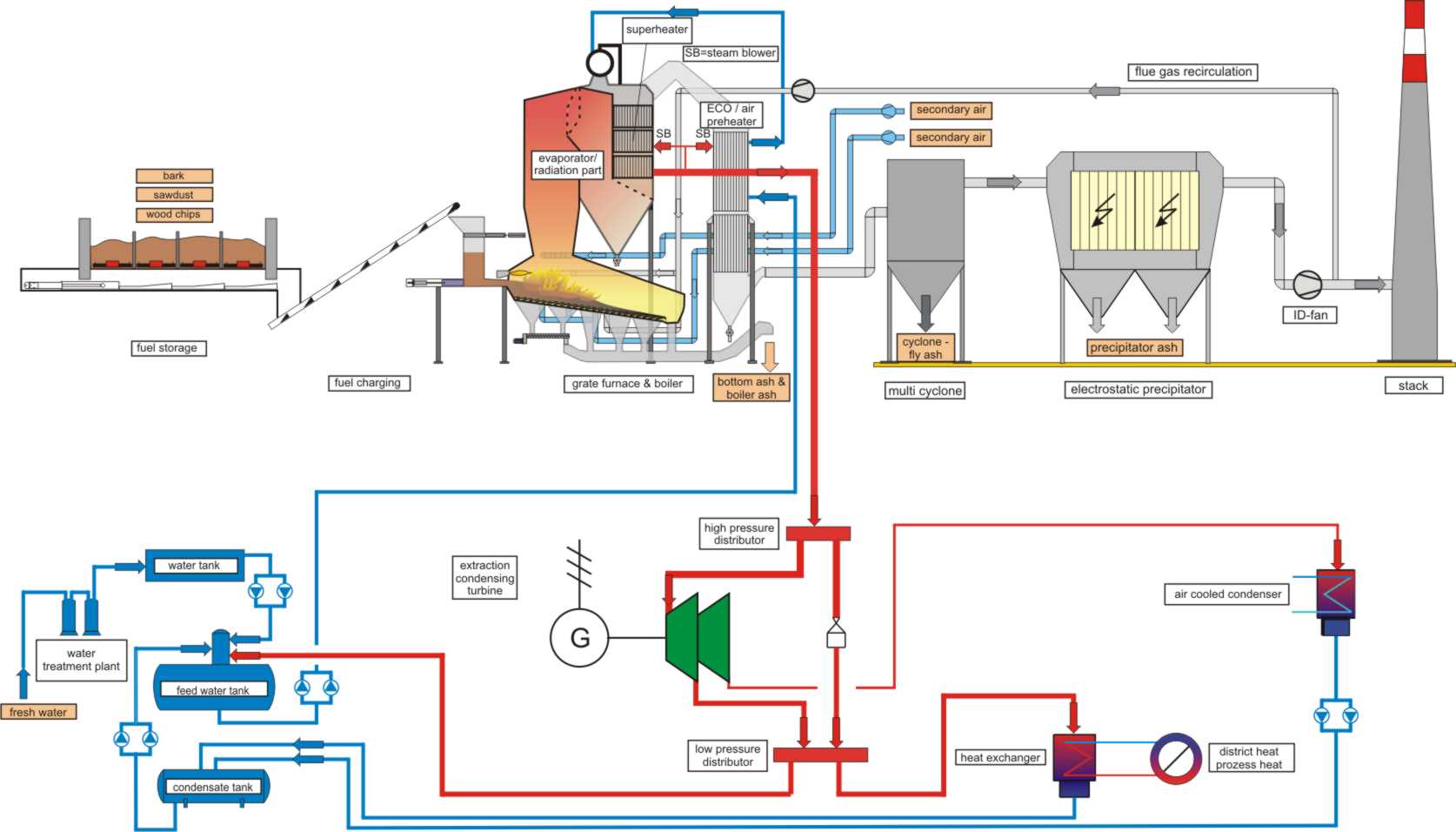 Figure 1: Simplified flow sheet of a CHP plant based on an extraction condensing turbine process
The fuel is fed from the fuel storage to the combustion unit by different conveying systems which are adapted to the different kind of fuels (bark, wood chips, sawdust, biomass residues) and the conditions on site regarding delivery of the fuel, intermediate storage and degree of automation.
In moving grate furnaces the fuel is fed onto the grate either by pushing the fuel horizontally onto the grate or by screw conveyers or spreader stoker systems. Moving grates are consisting of fixed and moveable rows of grate bars.
The steam boiler is a combination of the evaporator, superheater and economiser situated in a boiler (often a four-pass type is used; see Figure 2). Some manufacturers implement additionally combustion air pre-heaters in the flue gas path. Others use steam or hot water for combustion air pre-heating.
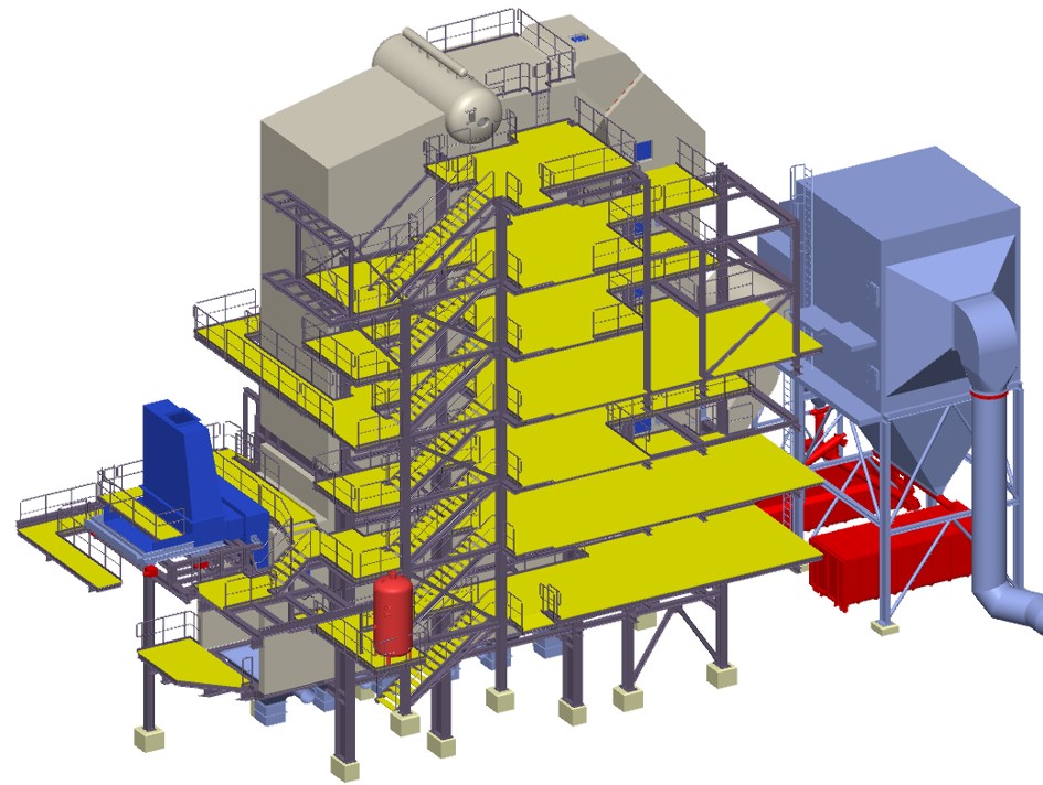
Figure 2: Moving grate furnace with water tube boiler and flue gas cleaning system
After the water-steam circuit, feed-water is heated in the economiser to a temperature below the saturation point. The economiser is on the water side the first heat-exchanger of the boiler collecting heat from the flue gas downstream superheater exit.
In the combustion chamber, the chemically bounded energy of the fuel is released and transferred across the boiler and heat-exchanger walls to the water steam circuit. The heated water is then evaporated in the boiler evaporator and attains the steam drum. Usually the evaporator tubes constitute partly the combustion chamber walls and are aligned in a vertical arrangement. The steam drum is located outside the flue gas flow. From the steam drum the saturated steam flows to the superheater section.
The superheaters extract heat from the hot flue gas to produce superheated steam. But it is necessary to turn one´s attention to possible high temperature corrosion mechanisms that may occur. Therefore, the position and flue gas inlet temperature into the superheaters have to be determined according to the biomass fuel used.
After the boiler multi-cyclones and electrostatic precipitators or fabric filters are commonly used to remove dust from the flue gas.
Superheated steam at high pressure and high temperature is ducted via pipes to the steam turbine where it is consumed and de-pressurised.
From the extraction condensing turbine steam is extracted at a pressure state which is pre-determined by the heat consumers. The main part of this extracted pressure steam passes to the heating condenser and a smaller part is used to transfer heat to the feed-water. The rest of the steam expands in the low pressure part of the turbine to the condenser pressure state and is then cooled at constant pressure. Depending on the conditions on site dry air-cooled condensers or water cooled condensers are installed.
In general the turbogenerator unit includes the modules:
- steam turbine
- gearbox/generator unit
- lubricating oil system
- control oil system
- measuring and control system
De-ionised water is used for the water steam circuit in order to keep an undisturbed operation. In the water treatment unit dissolved and undissolved impurities of the natural water must be removed.
Losses in the water-steam circuit caused by blow-down and sampling are replenished by de-ionised water from the feed water treatment unit.
Relevant technical data and efficiencies of the steam turbine process
If only chemically untreated wood-like biomass is used, according to present state-of-the-art, live steam temperatures up to approximately 540°C are achieved. When using waste wood, the live steam temperatures must be lowered to approximately 450 °C to avoid increased ash deposit formation und corrosion.
The attainable annual electric efficiency (= annual electricity production / annual fuel input based on its net caloric value) depends on the live steam parameters (temperature, pressure) and on the other hand on the necessary temperature level for the process and/or district heat consumers. Annual electric efficiencies range usually between 18 and 30 % for biomass CHP plants in the capacity range between 2 and 25 MWel.
Steam parameters and electric capacities at steam turbine processes:
- Live steam temperature: 450 – 540 °C
- Live steam pressure: 20 – 100 bar(a)
- Live steam flow rate: 10 – 125 t/h
- Back pressure or extraction steam pressure: 1 – 10 bar
- Exhaust steam pressure: 0.05 – 0.60 bar(a)
- Electric capacity: 2 – 25 MWel
- Annual electric efficiency: 18 – 30 % (related to NCV of the fuel)