
![]()
ORC Process
Download PDF Presentation Heat Recovery+Improvement of Efficiency
Description of the ORC technology for biomass combined heat and power plants as well as further possibilities for process integration
The ORC technology is based on a long-term development with the aim to efficiently use solar energy, geothermal energy as well as energy from biomass in decentralised units. The principle of electricity generation by means of an ORC process corresponds to the conventional Rankine process. The substantial difference is that an organic working medium (hydrocarbons such as iso-pentane, iso-octane, toluene or silicon oil) with favourable thermodynamic properties at lower temperatures and pressures is used instead of water - hence the name Organic Rankine Cycle (ORC). The right choice of the organic working medium used is very important for an optimised operation of the ORC process. Considering the framework conditions given for biomass Combined Heat and Power applications (CHP plants), silicon oil is the most appropriate working fluid.
Working principle and implementation in the biomass CHP plant
Figure 1 illustrates a possible implementation of the ORC process based on a biomass CHP plant. The energy produced by biomass combustion is transferred from a thermal oil boiler (inclusive thermal oil economiser) via a thermal oil cycle to the ORC process. Thermal oil is used as a heat transfer medium because the temperature required for operating the ORC process (thermal oil feed temperature 300°C) can be achieved while operating the thermal oil boiler practically at atmospheric pressure (therefore, no constant boiler supervision is needed). The pressurised organic working fluid is vaporised and slightly superheated in the evaporator by the energy supplied from the thermal oil cycle. The steam is expanded in an axial turbine which is directly connected to an asynchronous generator (no intermediate gear box is necessary). Subsequently, the expanded silicon oil passes through a regenerator (where in-cycle heat recuperation takes place which increases the electric efficiency) before it enters the condenser. The condensation of the working medium takes place at a temperature level which allows the heat recovered to be utilised as district or process heat (hot water feed temperature about 80 to 100°C). The liquid working medium then passes the feed pumps in order to regain the appropriate pressure level of the hot end of the cycle, passes the regenerator and returns to the evaporator.
The flue gas from the outlet of the thermal oil boiler (respectively from the thermal oil economiser) is cooled down from about 280°C to about 160°C by an efficient heat recovery system (for example combustion air pre-heater and hot water economiser). Subsequently, the flue gas is cleaned in a multi-cyclone (precipitation of larger dust particles) followed by a respective flue gas cleaning unit (in many cases an electrostatic precipitator or a flue gas condensation unit is installed). After the flue gas cleaning unit the flue gas enters – cleaned according to the local regulations –the stack.
Figure 1: Schematic illustration of a biomass CHP plant based on ORC technology
Figure 2: View of selected components of an ORC unit (1,000 kWel)
Explanations: left: Regenerator; bottom right: Evaporator and Pre-heater; top right: Turbine
Figure 3: Schematic illustration of the modular design as well as description of the main components of a 1,000 kWel ORC unit
Explanations: 1: Regenerator; 2: Condenser; 3: Turbine; 4: Electric generator; 5: Circulation pump; 6: Pre-heater; 7: Evaporator; 8: Hot water outlet; 9: Hot water inlet; 10: Thermal oil inlet; 11: Thermal oil outlet; source: TURBODEN Srl, Brescia
Figure 4: Schematic illustration of the modular design as well as description of the main components of of a 1,500 kWel ORC unit
Explanations: 1: Regenerator and condenser; 2: Turbine; 3: Electric generator; 4: Circulation pump; 5: Pre-heater; 6: Evaporator; 7: Hot water outlet; 8: Hot water inlet; 9: Thermal oil inlet; 10: Thermal oil outlet; source: TURBODEN Srl, Brescia
The ORC process can be designed in such a way that hot water feed temperatures between 80 and 100°C as well as a temperature differential between feed and return in a range of 15 to 50°C are possible. Therefore, the return temperatures vary between 50 and 85°C. On this basis the exact level of the hot water feed temperature required can be perfectly adjusted to the design requirements of the customers. For the hydronic implementation of the ORC unit, the hot water economiser should be installed after the ORC process (see Figure 1), in order to keep the level of the hot water feed temperature from the ORC as low as possible. The lower the hot water feed temperature at the condenser outlet, the higher is the electric efficiency.
Figure 2 shows some selected components of a 1,000 kWel ORC unit completely mounted and insulated. The modular design as well as the description of the main components of the ORC unit is given in Figures 3 and 4. It is important to outline, that the scheme given in Figure 4 is suitable for a module size corresponding to a nominal electric power of 1,500 kW and that this design concept (configuration, space needed) is different to the one which is given in Figure 3. In principle, the design given in Figure 3 is valid for ORC units between 400 kWel and 1,100 kWel.
Efficiencies and relevant technical data of the ORC process
The implementation of the ORC process into the overall plant should always be carried out in consideration of an as high as possible production of electric energy and simultaneously a secure supply of hot water feed temperatures required from the heat consumers.
Based on the requirements from the heat consumers and the plant design chosen, the resulting hot water temperatures at the ORC condenser are determined for the nominal design point (for example: feed temperature 80°C; return temperature 60°C) and allow a net electric efficiency of about 15% (based on the primary energy input related to the NCV of the biomass fuel). In Figure 5, the energy flow chart of a 1,000 kWel ORC unit integrated in a biomass CHP plant is given for nominal load conditions.
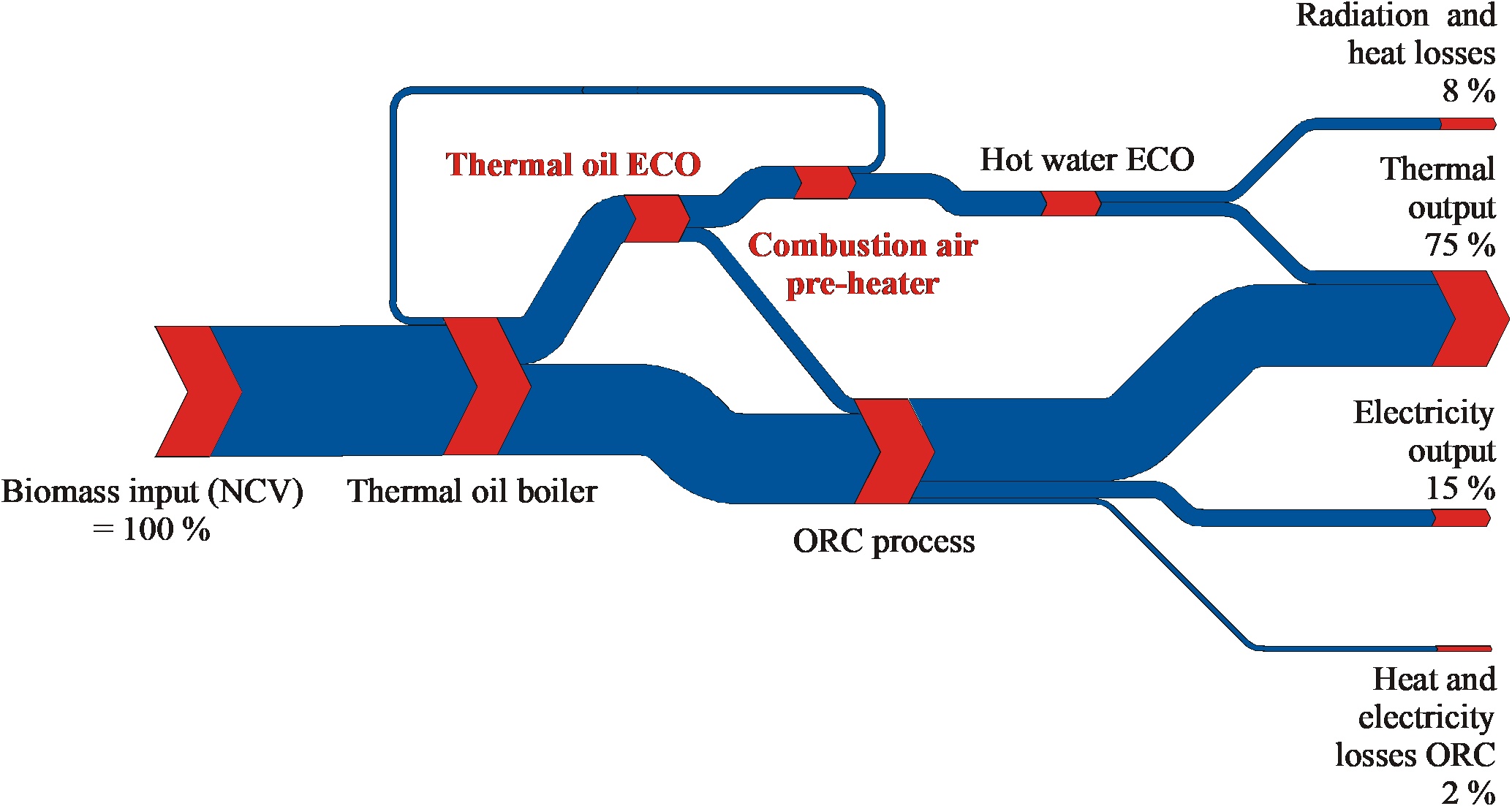
Figure 5: Energy flow chart of an ORC process (1,000 kWel) integrated in a biomass CHP plant at nominal load
Since decentralised biomass combined heat and power plants are usually operated in a heat controlled mode - for economic as well as energetic reasons – the partial load behaviour and the partial load efficiency of the ORC process is very important. Due to the slowly rotating axial turbine installed and because of the thermodynamic properties of the organic working medium used, the partial load behaviour of the ORC process is excellent. At 40% of the net electric power of the ORC unit, the net electric efficiency still amounts to 85% of the nominal value, which was also confirmed by the evaluation of measurement data from various realised projects (see Figure 6). This circumstance is a substantial advantage of the ORC process in comparison to steam turbines and also steam engines, which show a stronger efficiency decrease at partial load.
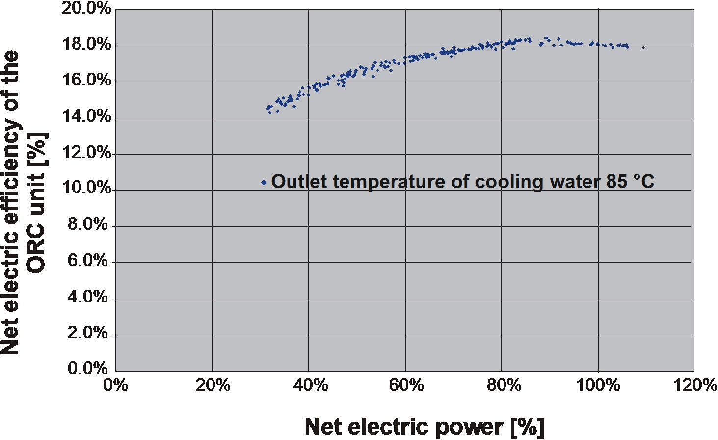
Figure 6: Trend of the net electric efficiency of an ORC process (1,000 kWel) in a biomass CHP plant versus the load condition of the ORC unit
Explanations: net electric efficiency = net electric power / thermal power input supplied by the thermal oil; the load condition is given in percent and based on the net electric power of the ORC process; the data mentioned are based on a hot water feed temperature of 85°C
The axial turbine, which is installed in the ORC process (for example see Figure 7), is optimised for small-scale CHP plants and works with a low circumferential speed and rotational frequency, hence a lower mechanical stress. The turbine also allows a direct drive of the generator without an intermediate gear box, which increases the electric efficiency. Because of the smaller specific enthalpy difference within the turbine in comparison to conventional water-steam-processes, a basic and robust turbine construction is possible. The factors mentioned above lead to improved life-cycle periods of the turbine as well as a high availability of the ORC unit.
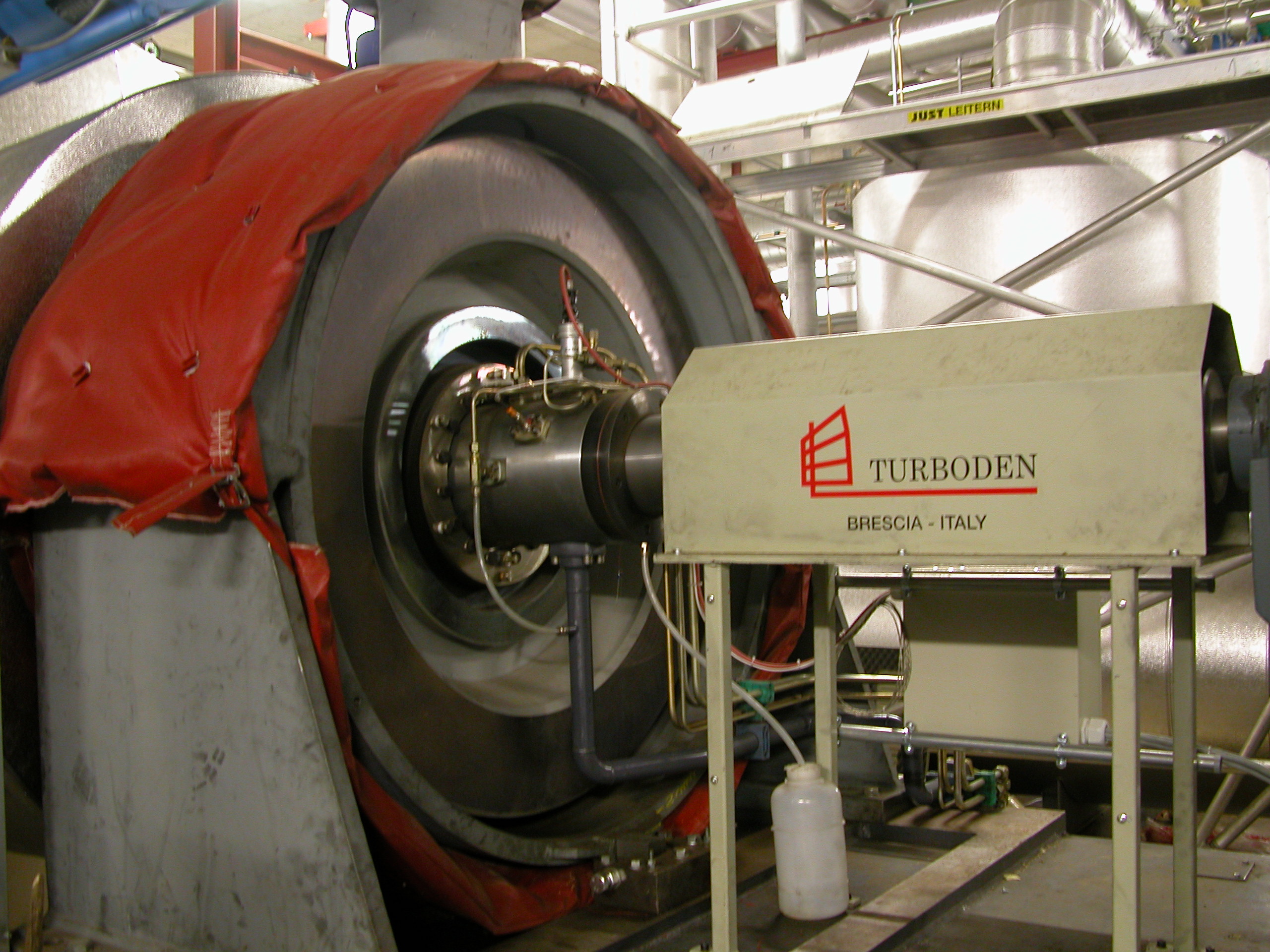
Figure 7: View of the axial turbine of a 1,500 kWel ORC unit
Safety aspects, process control, human resources needed
Particularly important are the high safety aspects of the ORC process. All welding seams of the pressure vessels of the ORC unit are 100% X-ray tested as well as tested at maximum pressure level. This way the time periods between recurring internal inspections by a notified body can be extended. In this context, BIOS BIOENERGIESYSTEME GmbH has worked out a complete safety concept. This work was carried out for several projects together with the manufacturing companies of the thermal oil as well as the silicon oil cycle (ORC process). These documents are important and valuable, not only for the operating staff of biomass CHP plants, but also for external experts (local authorities, technical inspectors, etc.), in order to understand and efficiently implement the measures required in case of failures or damages of these complex processes. Furthermore, older systems were assessed with regard to the safety-related equipment and subsequently modified and thus brought up to date with the state-of-the-art.
The process control of the ORC unit is installed over a storage-programmable logic controller (PLC), which allows the fully automated start-up and shutdown as well as the synchronisation to the public electric grid of the local utility. Load alternations of the ORC unit are also controlled fully automated over the hot water feed temperature at the outlet of the ORC condenser. It is not necessary that operation staff is at the site permanently, because also a shutdown procedure is carried out of the process control system alone. The same is true for the start-up procedures. In a pre-heated or still hot condition of the ORC unit, the ORC process can be coupled to the public electric grid within 15 minutes (after processing the continuous security tests required). A continuous operation of the ORC unit is possible between 10% and 100% of the nominal load.
As already mentioned the ORC process is connected with the thermal oil boiler (inclusive the thermal oil economiser) via a thermal oil cycle. The heat transfer medium (thermal oil) allows an operation of the thermal oil boiler practically at atmospheric pressure ranges despite high operation temperatures required. Therefore, no constant boiler supervision is needed, which results in lower personal costs in comparison to the conventional steam boiler operation. Furthermore, a water treatment is not necessary for an ORC unit, which would be the case for water / steam as a heat transfer medium. The operation of the ORC process (as mentioned above) is not under the regulations of the steam boiler operation law.
ORC processes are characterised by a high reliability and low numbers of breakdowns, which is confirmed through the experiences gained from the applications in the area of geothermal energy production. Since the ORC process is operated as a closed cycle and therefore no losses of the working fluid occur, the operating costs are relatively low. There are only moderate costs for lubricants, maintenance and personnel. Because of the fully automated process control, a practically unmanned operation of the ORC process is possible. Regarding maintenance required, it is common practice to have an inspection once a year from the manufacturing company, which lasts 1 to 2 days. Eventually occurring alarms are easily traceable by the process visualisation system and the operation data acquisition system via the user interface of the process control system (work station with monitor and printer) and can be forwarded in time to the operating staff over a GSM system.
Optimised variant of the ORC process
The newly designed ORC process with a split condensate cycle is an interesting option to further optimise the system. This new technological approach utilises additional heat from the flue gas in a second thermal oil economiser, which is supplied to the ORC process (to be more accurate: to the regenerator, see Figure 8). Calculations performed as well as measurements indicate that this technology can enhance the electric plant efficiency by 4 % (same specific heat exchanger area) to 8% (increased specific heat exchanger area).
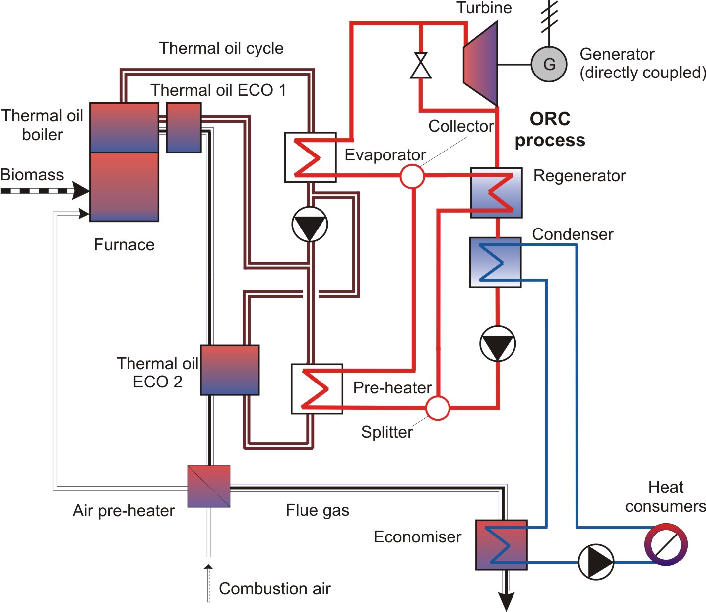
Figure 8: Schematic illustration of the modified ORC process with a branched condensate cycle
Further possibilities for optimisation
The following paragraphs give a short overview of selected further short- and long-term possibilities for optimisation of the ORC process. The focus of future developments will concentrate on improving the electric efficiency of the ORC unit. For detailed information about these improvement potentials, please see the publication section.
A possibility to improve the electric plant efficiency of the ORC process is given by an increase of the thermal oil temperatures (from 300/250 to 320/270 °C). This modified operation leads to an enhanced electric plant efficiency of approximately 3% (at the same temperature difference between thermal oil feed and return temperature). But it has to be stated that 2 important consequences are linked to this step. First of all the lifetime of the thermal oil used will decrease, because of the higher operation temperatures. Second, several components of the ORC process (especially the heat exchangers) must be modified in order to implement this measure effectively, which leads to higher investment costs. This second disadvantage could be compensated, if increased temperatures are necessary in the cooling cycle (feed water temperature at the condenser up to 120°C). In this case the expensive modifications of the ORC system are not necessary. Additionally, a further possibility is given by running the ORC process with elevated thermal oil feed temperature and simultaneously with a higher temperature difference between feed and return (320/250°C); these measures result in an efficiency improvement of about 2 % as well as a reduction of operating costs for the thermal oil pumps.
Another innovative process implementation is given by the possibility to implement the ORC process in a fluidised-bed steam gasification process coupled to gas engines (see Figure 9). This seems to be meaningful for CHP plants above a nominal load of 2.5 MWel from an energetic as well as economic point of view. By coupling these different CHP technologies, an improvement of the electric plant efficiency of about 20 % can be expected.
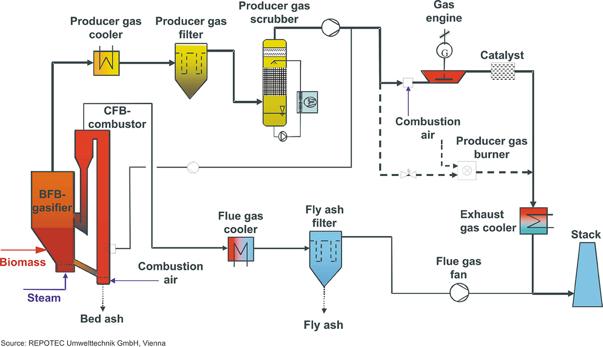
Figure 9: Schematic illustration of the integration of an ORC process into a fluidised-bed-steam-gasification process operated with gas engines
Source: REPOTEC Umwelttechnik GmbH, Vienna and BIOS BIOENERGIESYSTEME GmbH, Graz
A further possibility is the direct integration of the ORC circuit into the biomass combustion system. In this concept, the thermal oil intermediate circuit is not needed and the working medium is evaporated directly by the flue gas. The elimination of the thermal oil circuit reduces the investment costs and also the operating costs due to the thermal oil pumps and the thermal losses of the intermediate circuit. On the other hand, flue gas recirculation is needed, since the gas inlet temperature into the ORC must be below 650°C. Depending on the general conditions, an economic advantage of the direct system compared to the system with intermediate circuit can arise. A disadvantage is the increased risk potential of the circulating medium of the ORC compared to the thermal oil, which is particularly relevant due to the risk of corrosion and erosion of the heat exchangers in biomass combustion plants.
In addition to the integration of ORC modules in new projects for CHP plants, the ORC technology is very suitable for power production from already existing industrial waste heat or excess heat. Industrial waste heat mostly is available in form of hot gases, which can be transferred to the ORC either directly or indirectly (via an intermediate thermal oil or steam circuit) depending on the temperature level and gas quality existing. Especially in cement, building material, steel and food industries, unused excess heat often is available as low pressure steam or hot gas which also can be fed into the ORC directly as hot source. According to the temperature range and the requirements of the industrial plant, the off-heat of the ORC could also be used for internal or external low temperature heat. Thus, industrial plants often can reduce very efficiently their primary fossil energy demand and therefore their local CO2 emissions as well as their purchased electricity demand.
Strengths of the ORC technology
- Large range of size per ORC unit –> 100 to 20,000 kWel
- Excellent partial load behaviour
- Ability for quick load alternations (in particular an advantage for heat controlled operation and achieving high annual utilisation rates)
- Mature and reliable technology
- No danger of droplet erosion on turbine blades (because of the favourable thermodynamic properties of the working medium used)
- No constant steam boiler supervision is needed
- High degree of automation
- Low maintenance costs
- The implementation of ORC units in existing biomass combustion plants is relatively easy
- Further interesting possibilities for optimisation are given