

Screw-Type Engine
Download Poster Screw-type engine
Description of the screw-type steam engine cycle in biomass-fired CHP plants
The screw-type engine cycle is based on the conventional Rankine process. In opposite to the steam turbine process the steam is expanded in a screw-type engine, which is connected to a generator producing electric power.
The screw-type engine is derived from the screw compressor and is consequently based on comprehensive engine Know-How. Screw-type engines are suitable for biomass CHP plants in the range of 200 to 2,500 kWel, where steam parameters can vary, due to variations of the fuel water content and the kind of biomass fuel used, and where a simple and heavy duty design is needed causing low operating and maintenance costs.
Principle of the screw-type engine technology
The screw-type engine is a displacement rotary engine. Similar to piston engines, displacement-type engines are characterised by a closed working chamber. The volume of the working chamber changes cyclically, which leads to a decrease of the energy content of the fluid in the chamber. The main parts of a screw-type engine are the male rotor, the female rotor and a casing, which together form a V-shaped working chamber whose volume depends solely on the angle of rotation. The steam enters the casing through the intake port in the passage formed between the tips of the rotor teeth. During rotation the volume of the chamber increases. Intake is finished when the rotor faces pass the guiding edges and the chamber is separated from the intake port. At this stage steam expansion starts and mechanical power is produced at the output shaft. During expansion the volume of the chamber continues to increase, whereas the energy content of the fluid decreases. This process continues until the exhaust process starts and the steam is extruded. It leaves the machine through the exhaust port. How often this process takes place during one rotation of the male rotor depends on the number of teeth on the male rotor. A detailed section drawing of the screw-type engine can be seen in Figure 1. The expansion process within a screw-type engine is shown in Figure 2.
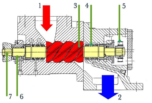
Figure 1: Section drawing of a screw-type engine
Explanations: 1...live steam inlet, 2...exhaust steam outlet, 3...male rotor, 4...shaft seal, 5...synchronisation gearwheels, 6...friction type bearing, 7...output shaft
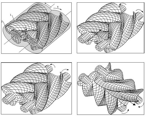
Figure 2: Expansion process within a screw-type engine
Explanations: 1... ... radial guiding edge, 2... ... axial guiding edge, 3... flow direction, 4... sense of rotation
The screw-type engine is a very compact machine with a long life time and low maintenance costs. It is insensitive to steam quality fluctuations and can be operated with superheated steam, saturated steam, wet steam and pressured hot water (see Figure 3). Water droplets in steam are no problem for screw-type steam machines in contrast to steam turbines and conventional steam engines.
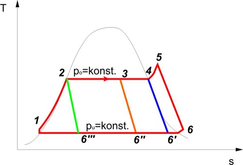
Figure 3: Possible cycles of operation of the screw-type engine process
Explanations: 5-6 ...superheated steam, 4-6'...saturated steam, 3-6''...wet steam, 2-6'''...pressured hot water
Implementation of the screw-type engine cycle into the biomass-fired CHP plant Hartberg
In Figure 4 the integration of the screw-type steam engine in the biomass CHP plant Hartberg (Austria) is schematically shown.
The biomass district heating plant (start of operation: 1987) is equipped with a water tube steam boiler and supplies process and district heat consumers via a network of pipes. In 2003 a superheater and a screw-type engine were implemented in the heating plant within an EU demonstration project. In the meantime more than 15 years of positive operation experience could be achieved.
The main parts of the process are the biomass-fired steam boiler (steam parameters: 26 bara, 225°C), the superheater (steam parameters: 25 bara, 255°C), the spray cooler behind the superheater as well as the screw-type engine utilising the steam for electricity production. After passing the screw-type engine the exhaust steam (parameters: 0.5-1.5 bara, 80-110°C) enters the condenser where the heat output produced from the screw-type engine CHP plant is transferred to the hot-water cycle which is used as district heat.
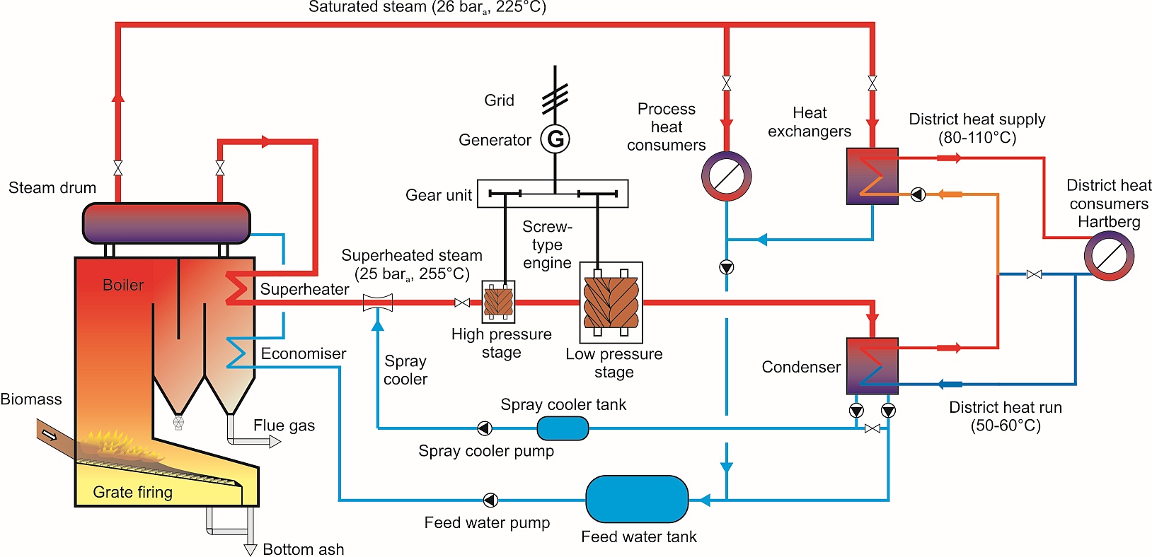
Figure 4: Scheme of the integration of the screw-type steam engine in the biomass CHP plant Hartberg (Austria)
The screw-type engine in Hartberg is designed as a two-stage unit. The steam flows first through the smaller high-pressure stage, and then through the larger low-pressure stage (see Figure 5). Each stage is equipped with separate bearings and seals. Because of the high rotational speed of the screw engines a gear unit is installed, which powers the asynchronous generator. The gross nominal capacity of the screw-type engine is 730 kWel.
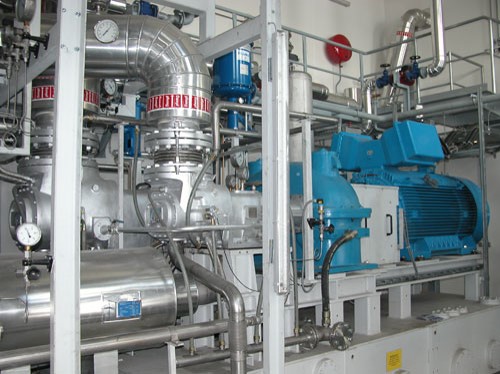
Figure 5: Screw-type steam engine of the biomass CHP plant Hartberg (net nominal electric capacity: 710 kWel)
Explanations: low-pressure stage (left), high-pressure stage (middle), gear unit and generator (right)
Figure 6 shows the annual heat output line of the district heat network loco heating plant, which formed the basis for a correct design of the CHP plant. Based on this curve and economic calculations, the biomass CHP plant was designed for basic and medium load operation in heat controlled mode (the aim of a high number of full-load operating hours as well as of a high overall efficiency can be achieved).
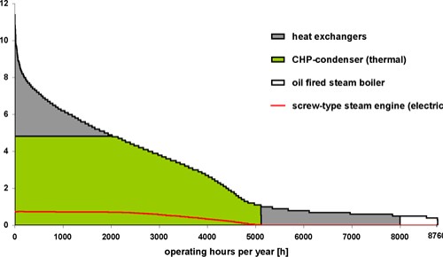
Figure 6: Annual heat output line of the district heat network loco heating plant Hartberg.
Technical data
Below the technical data of the EU demonstration project regarding the screw-type steam engine technology integration in the biomass CHP plant Hartberg are outlined.
Nominal data of the boiler unit:
- Nominal load of the water tube steam boiler 18 MW
- Boiler pressure (approved) 32 barg
Nominal data of the CHP module:
- Steam power input 5,640 kW
- Steam flow rate 8.1 t/h
- Steam parameters inlet 255° C / 25 bara
- Gross nominal electric capacity 730 kW
- Net nominal electric capacity 710 kW
- Thermal capacity of the condenser 4,800 kW
- Steam parameters outlet 80-110° C / 0.5-1.5 bara
- Electric efficiency at nominal load operation 12.6 %
Energy balance of the CHP module:
- Thermal input (superheated steam) 22,560 MWh/a
- Produced electricity 2,780 MWh/a
- Thermal output at the condenser 19,230 MWh/a
Control system and safety equipment
The screw-type steam engine works in grid connected operation. Plant operation and start up are controlled fully automatically by an electronic control system and do not require additional staff.
To make sure that the oil in the bearings and the synchronising gear is separated from the steam in the working chamber, the labyrinth packing of the screw-type engine is designed in a way that fluids can be drained or supplied through various components (seals - connections). To separate the oil section from the water section, air is injected under slight pressure. Some parts of the seal are connected in order to make sure that no air can enter the working chamber if there is a vacuum in the condenser.
Advantages of the screw-type engine process
Screw-type steam engines for small-scale biomass CHP applications have a number of advantages compared to conventional steam turbines and steam engines:
- Comparatively high electric efficiency for small-scale CHP units (< 1,000 kWel)
- The screw-type engine has a very good partial-load efficiency over a wide range of load conditions
- Load fluctuations between 30 and 100 % of nominal electric power production are no problem
- The screw-type engine is insensitive to steam quality fluctuations. Even water droplets in steam, which can occur in a simple boiler due to malfunction or changes of fuel quality, do not cause any problems in screw-type engines
- The steam cycle and the oil cycle are completely separated by an air-lock system
- The fully automatic operation and easy handling saves staff costs
- The screw-type engine is a very compact machine and causes low maintenance costs
